PSEB Class 10 Physics Solutions For Chapter 1 Light-Reflection And Refraction
Light
Light is the form of energy that enables us to see. An object reflects light that falls on it. We are able to see the object when this reflected light is received by our eyes.
Properties Of Light
- Light travels in a straight line. Due to this, light casts a shadow of the object placed in its path.
- Light is an electromagnetic wave. It does not require any medium to travel.
- The speed of light is maximum in a vacuum. It is 3×10⁸ ms-1.
- Light has a dual nature, i.e., particle as well as wave nature.
- When light falls on an object, one or more of reflection, refraction, or absorption may happen.
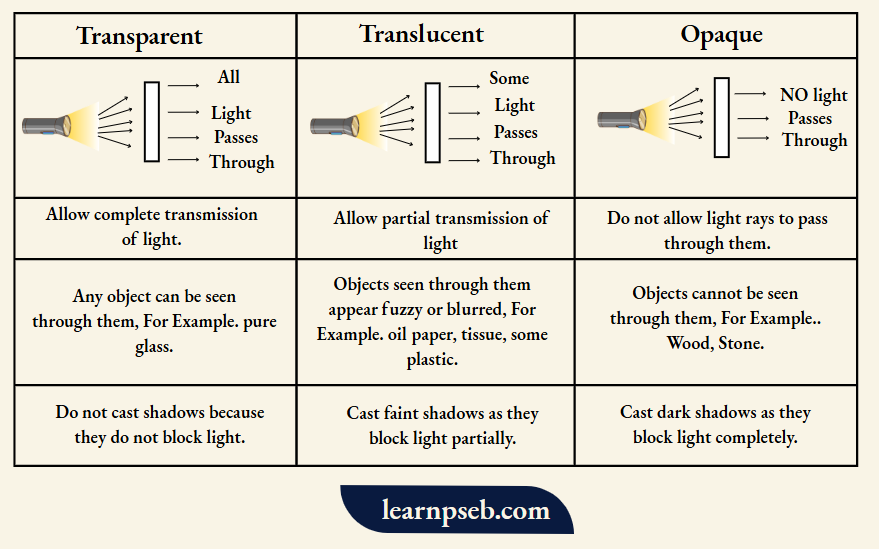
Types Of Materials Based On Absorption Of Light
Three types of materials based on absorption of light are Transparent, Translucent, and Opaque.
PSEB Class 10 Physics Chapter 1 Light-Reflection And Refraction
Reflection Of Light
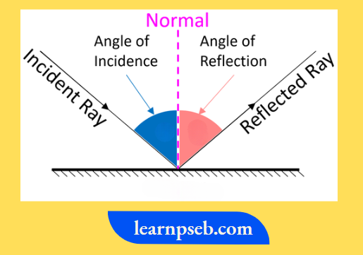
The phenomenon of bouncing back of light into the same medium, when it strikes a polished or smooth surface, is called reflection.
Incident Ray = Light ray which falls on the polished or smooth surface
Reflected ray = Light ray that gets bounced back from the polished or smooth surface.
Laws Of Reflection
Applicable to all types of reflecting surfaces, including spherical surfaces
- Angle of Incidence (∠i) = Angle of Reflection (∠r)
- Incident Ray, Normal to the angle of incidence, and Reflected Ray all lie in the same plane.
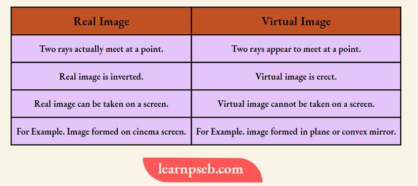
Image– It is the point at which two rays actually meet or appear to meet. An image can be of two types: Real or Virtual.
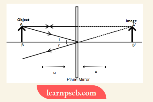
Characteristics Of the Image Formed By a Plane Mirror
- The image formed is Virtual- formed behind the mirror.
- Size of image = Size of Object
- Distance between mirror and object = Distance between mirror and image
- Laterally inverted- means the left side of the object appears right and the right side of the object appears left.
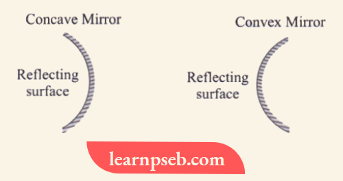
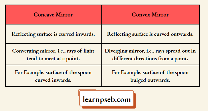
Spherical Mirrors
Mirrors whose reflecting surface forms part of the sphere are called spherical mirrors. They are of two types – Concave mirrors and Convex mirrors, as shown below:
Some Important Terms Used In Context To Spherical Mirrors
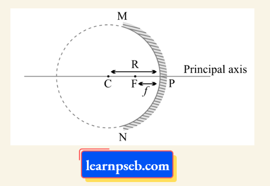
Pole (P) – Centre of the spherical mirror.
Centre of Curvature (C) – The centre of the hollow glass sphere of which the spherical mirror was a part.
Principal Axis – Line joining the pole (P) and centre of curvature (C).
Radius of Curvature (R) – Distance between pole (P) and centre of curvature (C).
Principal Focus (F) – Point on the principal axis where all rays actually meet or appear to meet.
Focal Length (f) – Distance between pole (P) and principal focus (F).
Aperture (MN) – Effective diameter of the spherical mirror.
Relationship Between Focal Length (f) And Radius Of Curvature (R)
Focal Length (f) = Radius of Curvature (R)/2
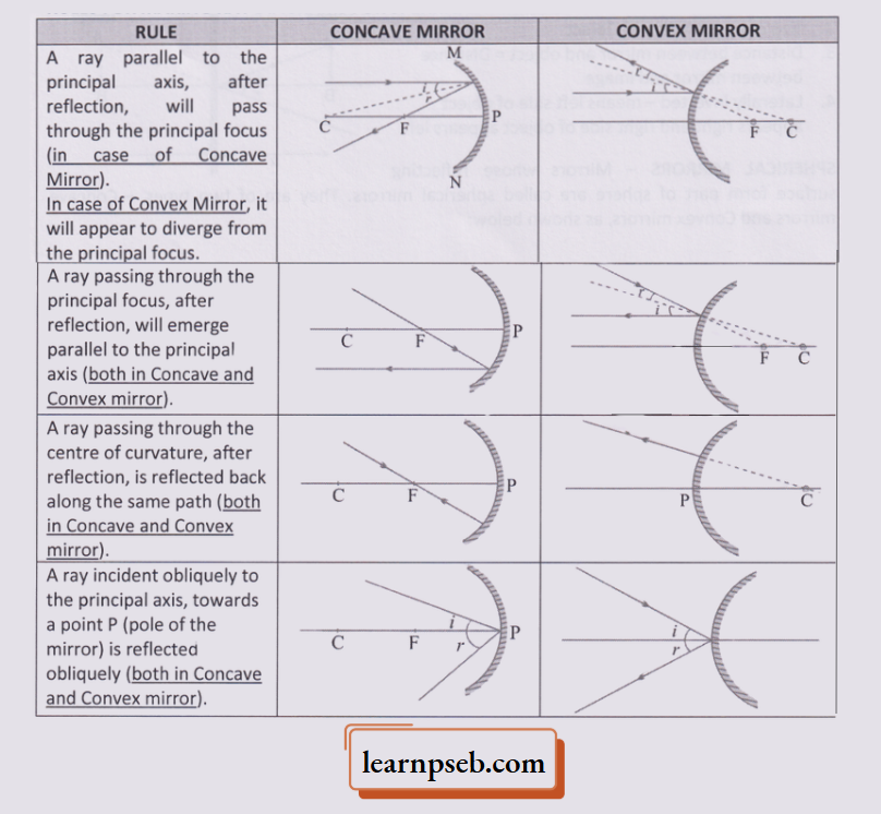
Rules For Making Ray Diagrams For Spehrical Mirrors
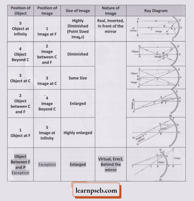
Simple Trick To Remember Image Formation By Concave Mirror
Step 1: Write position of object starting from infinity till between F and P.
Step 2: Write numbers 5, 4, 3, 2, 1 to all positions of object, and numbers 1, 2, 3, 4, 5 to all positions of image. (Note that numbers given to positions of objects are 5-1 and those given to image positions are 1-5. This is important point to be remembered).
Step 3: Comparing the numbers will give us the size of image, For Examle Since1 is very less than 5, size of image will be highly diminished, 2 is less than 4, therefore image will be diminished, and so on (as given in table below).
Note:
- For object position numbers 5, 4, 3, 2 and 1, image will be real and inverted.
- Last position of object is an exception- in this case image will be virtual and erect.
image
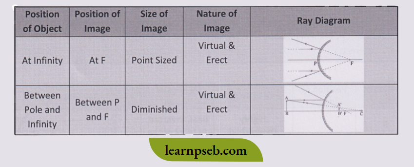
Simple Trick To Remember Image Formation By Convex Mirror
Important Note: Image formed by convex mirror is always virtual, erect and small in size.
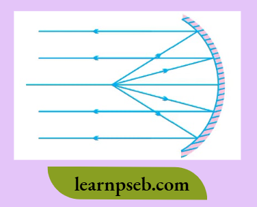
Uses Of Concave Mirrors
1. Used in torches, search-lights and vehicles headlights to get powerful parallel beams of light as shown in diagram:
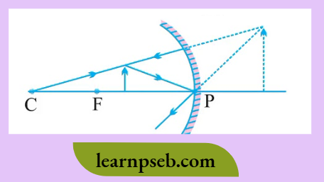
2. Used as shaving mirrors to see a larger image of the face, and also used by dentists to see large images of the teeth of patients. For this, the object has to be placed between pole and focus, as shown in figure:
PSEB Class 10 Physics Solutions Chapter 1
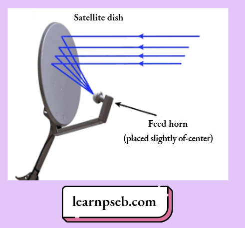
3. Large concave mirrors are used to concentrate sunlight to produce heat in solar furnaces.
4. Used as satellite dish TV antennas as shown in figure:
Uses Of Convex Mirrors
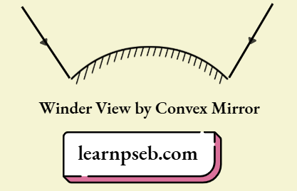
1. Used as rear-view (wing) mirrors in vehicles because:
- They always give an erect, though diminished, image.
- They have a wider field of view as they are curved outwards, as shown in figure.
2. Used at blind turns and points of merging traffic to give view of traffic from both sides.
3. Used in shops as security mirror.
New Cartesian Sign Conventions – For Reflection By Spherical Mirrors
In the New Cartesian Sign Convention,
- Pole (P) of the mirror is taken as the origin.
- Principal axis of the mirror is taken as the x-axis of the coordinate system.
- The New Cartesian Sign Convention are summarized in the figure provided below (For details, please refer points 1-5 given after the figure):
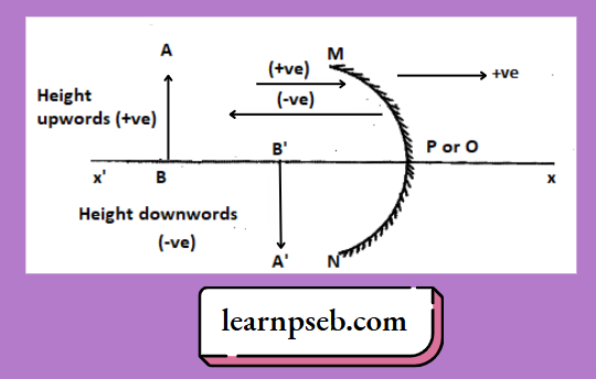
- Object is always placed to the left of the mirror, i.e, light from the object falls on the mirror from the left-hand side.
- All distances parallel to the principal axis are measured from the pole of the mirror.
- All the distances measured to the right of the origin (along + x-axis) are taken as positive while those measured to the left of the origin (along- x-axis) are taken as negative.
- Distances measured perpendicular to and above the principal axis (along + y-axis) are taken as positive.
- Distances measured perpendicular to and below the principal axis (along -y-axis) are taken as negative.
Conclusions From New Cartesian Sign Conventions For Spherical Mirrors
Distance of Object from Mirror (u) = Always Negative
Focal length of Concave Mirror (f) = Negative
Focal length of Convex Mirror (f) = Positive
Mirror Formula
It gives the relation between distance of object, distance of image and focal length of the mirror. According to mirror formula
∴ \(\frac{1}{v}+\frac{1}{u}=\frac{1}{f}\)
Where, u = distance of object from pole, v = distance of image from pole, and f = focal length of mirror.
Mirror formula is valid for plane mirrors as well as spherical mirrors for all positions of the object.
Important Note: For solving numerical problems, New Cartesian Sign Conventions must be considered while substituting values for u. v, f (or R. if focal length is calculated using relation f = R/2) in the mirror formula.
Magnification Of Spherical Mirrors
Magnification (m) is defined as the ratio of height of image to the height of object.
∴ \(m=\frac{\text { Height of image }}{\text { Height of object }}=\frac{h_i}{h_o}=-\frac{v}{u}\)
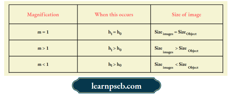
Simple Trick To Find The Type Or Size Of Image From Value Of Magnification
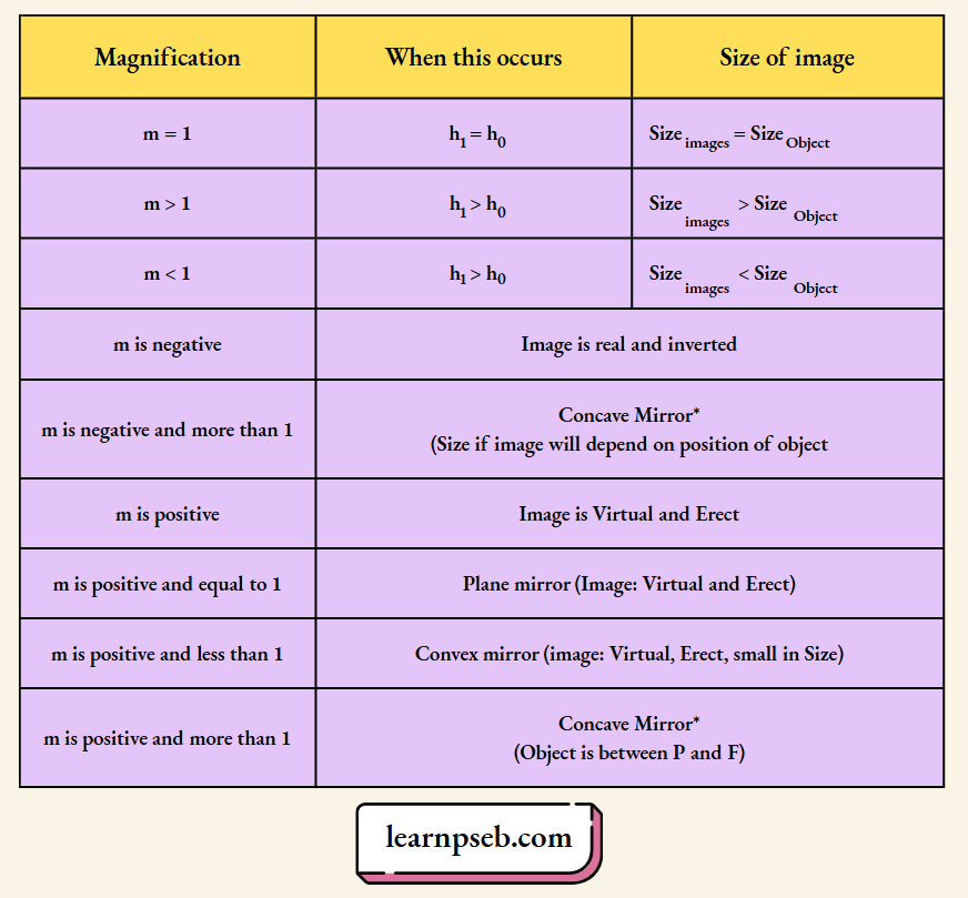
Important Note:
- Magnification of convex mirror is always negative.
- Magnification of concave mirror can be positive or negative depending on the position of the object.
Refraction Of Light
The phenomenon of bending of light when it enters obliquely from one transparent medium into another is called refraction of light. Refraction occurs due to change in speed of light in different media.
Light-Reflection And Refraction PSEB Class 10 Notes
Bending Of Light In Refraction
1. If a ray of light passes from a material in which it travels fast (rarer medium) into a material in which it travels slower (denser medium), then the light ray will bend towards the normal, i.e,
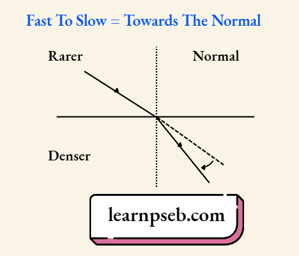
2. If a ray of light passes from a material in which it travels slow (denser medium) into a material in which it travels faster (rarer medium), then the light ray will bend away from the normal.
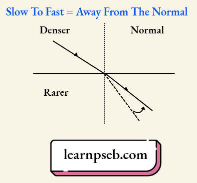
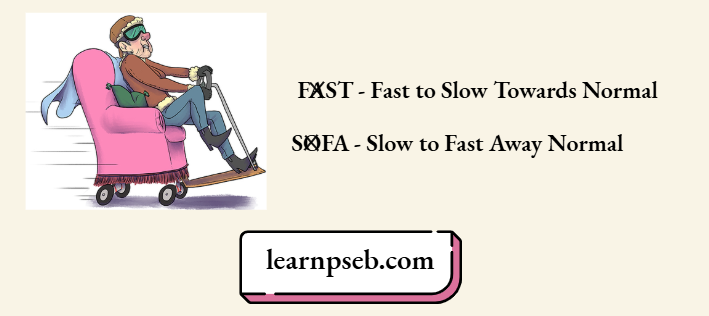
Simple Trick To Remember The Direction Of Bending Of Light In Refraction
Direction of bending of light in refraction can be easily remembered using the mnemonic “FAST SOFA”
3. Extent of bending of incident ray depends upon difference in refractive index between the two medium through which the ray is passing.
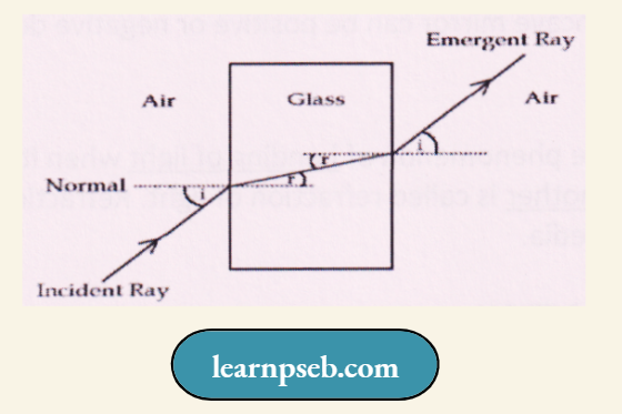
4. Emergent Ray is parallel to Incident Ray because the extent of bending of ray of light at the opposite parallel faces of the second medium (glass in this case) is equal and opposite as shown:
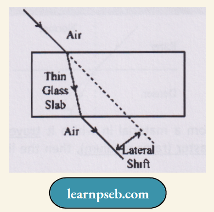
5. Perpendicular distance between the incident ray and the emergent ray is called lateral displacement or lateral shift (d). It depends upon:
- Thickness of the glass slab
- Refractive index of the glass slab
Refractive Index (n)
It is defined as the ratio of velocity of light in a given pair of media, i.e.,
∴ \(n=\frac{\text { Velocity of light in medium } 1}{\text { Velocity of light in medium } 2}\)
Points To Remember About Refractive Index
- Refractive index has no units because it is a ratio.
- Refractive index does not depend on the physical density of the medium, For Example kerosene having higher refractive index, is optically denser than water, although its mass density is less than water.
- Refractive index of water, nwater= 1.33, and refractive index of air, nair = 1. This means that the ratio of the speed of light in air and the speed of light in water is equal to 1.33.
- Refractive index of diamond is highest till date. Its value is 2.42. This means speed of light in diamond is 1/ 2.42 times less than the speed of light in air or vacuum.
- n21 means refractive index of 2nd medium with respect to 1st medium, whereas n21 means refractive index of 1st medium with respect to 2nd medium, i.e.,
∴ \(n_{21}=\frac{V_1}{V_2} \quad \text { whereas } \quad n_{12}=\frac{V_2}{V_1}\)
Absolute Refractive Index
It is the ratio of the speed of light in vacuum to the speed of light in the given medium, i.e.,
∴ \(n=\frac{c}{v}\)
where c = 3 x 10⁸ ms-1
Important Note: Absolute refractive index can never be less than 1 because the speed of light in any medium is always less than that in a vacuum.
Optically Rarer And Optically Denser Medium
Optically Rarer Medium – Medium with a lower value of refractive index
Optically Denser Medium – Medium with a higher value of refractive index
For Example – Out of Air and Glass, glass is denser medium while air is rarer medium.
PSEB Class 10 Physics Important Questions Chapter 1
Laws Of Refraction
The incident ray, the refracted ray and the normal to the interface of two transparent media at the point of incidence, all lie in the same plane.
The ratio of sine of angle of incidence to the sine of angle of refraction is a constant, for the light of a given colour and for the given pair of media. This law is also known as Snell’s law of refraction. Thus, according to Snell’s law,
∴ \(\frac{\sin i}{\sin r}=\text { constant }\)
The constant value is called the refractive index of the 2nd medium with respect to the 1st medium.
Snell’s law is true for 0 < i < 90°, where “i” is the angle of incidence.
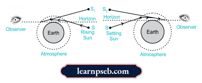
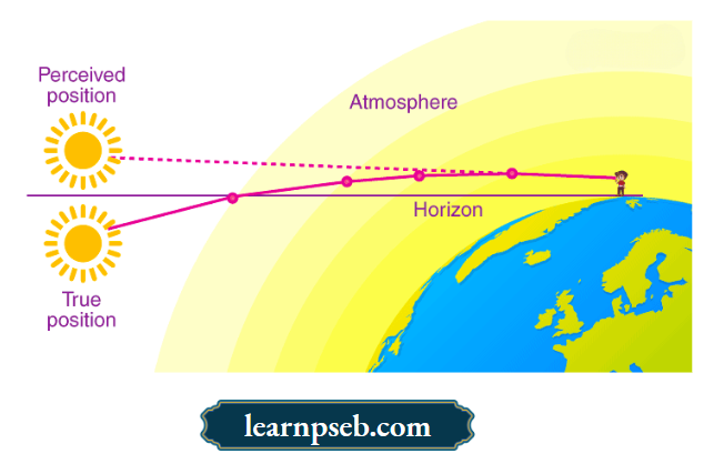
Some Common Examples Of Refraction
- The bottom of swimming pool appears higher due to refraction of light on entering water through air.
- A pencil partially immersed in water appears to be bent at the interface of air and water.
- When a thick glass slab is placed over some printed matter, the letters appear raised.
- Lemons placed in a glass tumbler appear bigger.
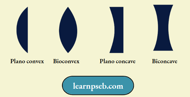
Spherical Lens – A transparent material bound by two surfaces, of which one or both surfaces are spherical, forms a lens.
Four Types Of Spherical Lens
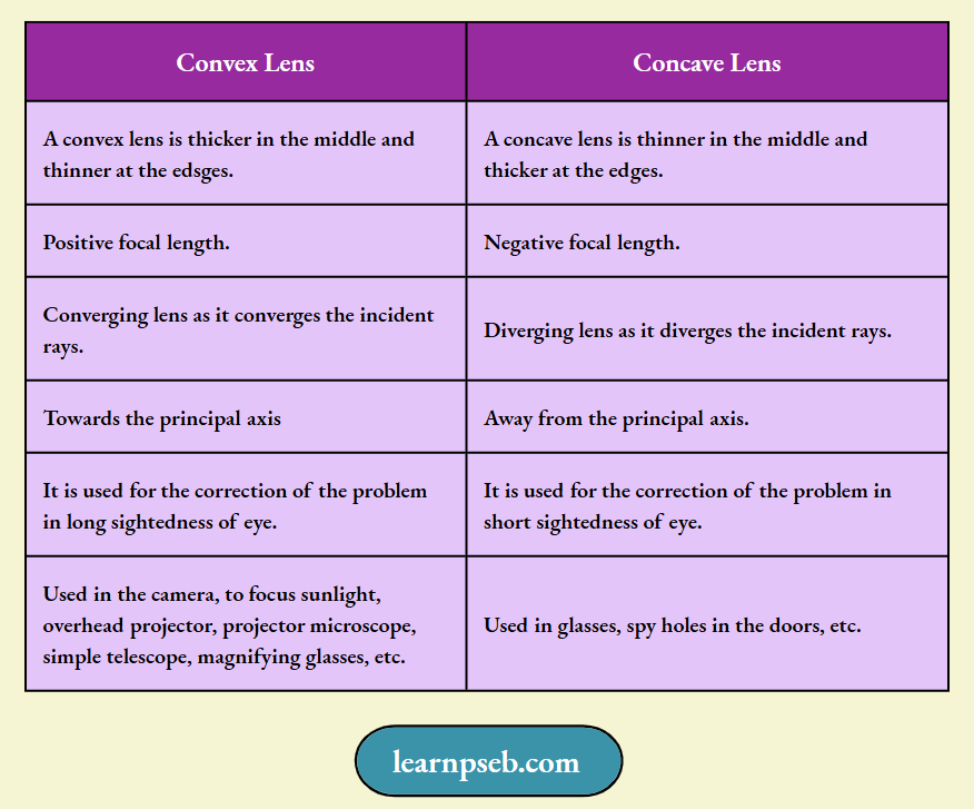
Difference Between Concave Lens And Convex Lens
Some Important Terms About Lens
Since both convex and concave lens have two spherical surfaces, it has two centres of curvature and two principal focus.
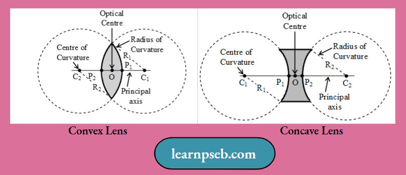
Centre of Curvature (C)– It is the centre of the sphere of which the lens forms a part. Because a lens has two spherical surfaces, it has two centres of curvature (C1 and C2 as shown in above figures).
Radius of Curvature (R)– It is the radius of the sphere of which the spherical surface of lens forms a part. R1 and R2 are radii of curvature in above figures.
Principal Axis (C1C2 – It is the line passing through the two centres of curvature (C1 and C2) of the lens.
Optical Centre (O) – If a ray of light is incident on a lens such that after refraction through the lens the emergent ray is parallel to the incident ray, then the point at which the refracted ray intersects, the principal axis is called the optical centre of the lens.
Note: Optical centre of lens coincides with the geometric centre of the lens when the radii of curvature of the two surfaces are equal.
Aperture– The diameter of the circular boundary of the lens is called its aperture.
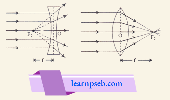
Principal Focus (F)– It is the point through which a parallel light after refraction passes through in the case of a convex lens and appears to pass through in the case of a concave lens. A lens has two focal points, because a lens has two refracting surfaces.
Focal Length (f)– It is the distance of the principal focus from the optical centre of a lens.
1. First Principal Focus (F1) and First Focal Length (f) – It is a fixed point on the principal axis such that rays starting from this point (in convex lens) or appearing to go towards this point (concave lens), after refraction through the lens, become parallel to the principal axis.
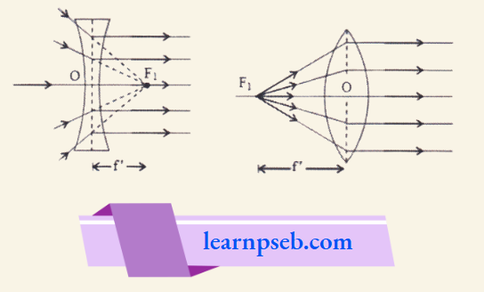
2. Second principal focus (F2) and second focal length (f’)– It is a fixed point on the principal axis such that the light ravs incident parallel to the principal axis, after refraction through the lens, either converge to this point (in convex lens) or appear to diverge from this point (in concave lens).
Important Note: If the medium on both sides of a lens is same, then first and second focal lengths are equal, i.e, f = f.
Rules For Image Formation By Lens
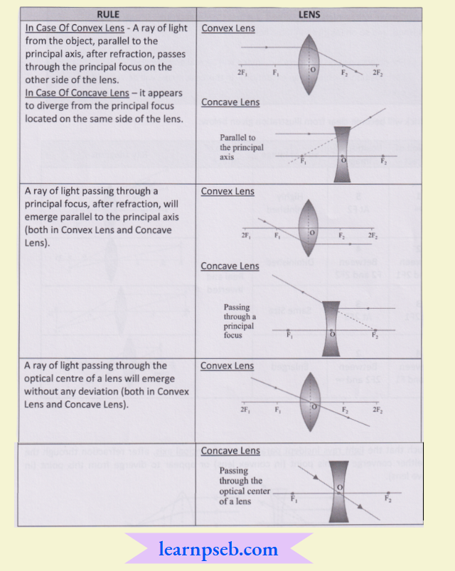
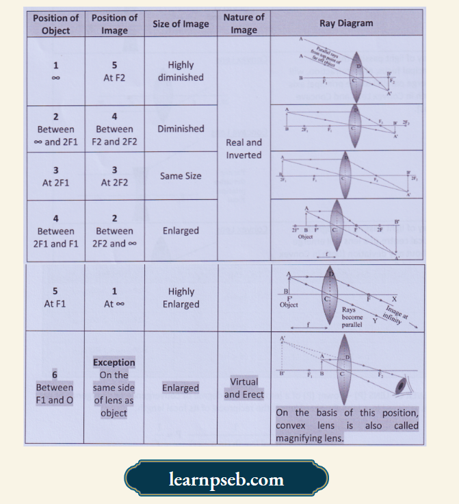
Simple Trick To Remember Image Formation By Convex Lens
Step 1: Write position of object starting from infinity till between F and P.
Step 2: Write numbers 1-6 to all positions of object, and numbers 5-1 to all positions of image as shown in figure.
Step 3: Comparing the numbers will give us the size of image, For Example. Since 1 is very less than 5, size of image will be highly diminished, 2 is less than 4, therefore image will be diminished, and so on (as given in table below).
Note:
- For object position numbers 5-1, image will be real and inverted.
- Last position of object is an exception- in this case image will be virtual and erect.
This trick will become clear from illustration given below:
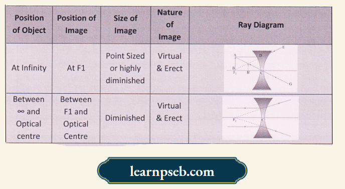
Simple Trick To Remember Image Formation By Concave Lens
Important Note: Image formed by Concave Lens is always Virtual. Erect and Small in size.
Lens Formula – It gives the relation between distance of object (u), distance of image (v) and focal length (f) for a lens. According to lens formula,
∴ \(\frac{1}{v}-\frac{1}{u}=\frac{1}{f}\)
Note: Lens formula is valid in all situations for all types of spherical lens.
Magnification Of Lens – It is defined as the ratio of the height of an image (hi) to the height of an object (h0). It is also written as ratio of distance of image from optical centre and distance of object from optical centre, i.e,
∴ \(m=\frac{h_i}{h_o}=\frac{V}{u}\)
Simple Trick To Find The Type or Size Of Image From Value Of Magnification
Power Of Lens (P)– Power (P) of a lens gives the degree of convergence or divergence of light rays achieved by a lens. Power of lens is the reciprocal of its focal length.
∴ \(\text { Power }=\frac{1}{\text { focal length (in meter) }} \mathrm{P}=\frac{1}{f}\)
SI unit of power of a lens is ‘dioptre’ (D). 1 dioptre is the power of a lens having focal length of lm, i.e., ID = lm-1.
PSEB Class 10 Science Chapter 1 Solutions
Points To Remember About Power Of Lens
- Power of a Convex Lens = Always positive
- Power of Concave Lens = Always Negative.
- Opticians use of the term power of lens instead of their focal lengths.
- In many optical instruments, number of lenses is combined to increase the magnification and sharpness of the image. In such instruments, the net power (P) of the lenses is given by the algebraic sum of the individual powers PI, P2, P3, … i.e, P = PI + P2 + P3 + …..
Chapter 1 Light-Reflection And Refraction Reason – Assertion Questions And Answers
The following questions consist of two statements- Assertion (A) and Reason (R). Answer these questionsby selecting the appropriate option given below:
- Both A and R are true and R is the correct explanation of A.
- Both A and R are true but R is not the correct explanation of A.
- A is true but R is false.
- A is false but R is true.
Question 1. Assertion (A): Large concave mirrors are used to concentrate sunlight to produce heat in solar cookers.
Reason (R): Concave mirror converges the light rays falling on it to a point.
Answer: 1. Both A and R are true and R is the correct explanation of A.
Question 2. Assertion (A): The focal length of the mirror is f and the distance of the object from the focus is u. The magnification of the mirror is f/u.
Reason (R): Magnification = + Size of image/ Size of object
Answer: 3. A is true but R is false.
Question 3. Assertion (A): For observing traffic at back, the driver mirror is a convex mirror.
Reason (R): A convex mirror has a much larger field of view than a plane mirror.
Answer: 1. Both A and R are true and R is the correct explanation of A.
Question 4. Assertion (A): Higher is the refractive index of a medium or denser the medium, lesser if the velocity of light in that medium.
Reason (R): Refractive index is inversely proportional to velocity.
Answer: 1. Both A and R are true and R is the correct explanation of A.
Question 5. Assertion: The image formed by a concave mirror is certainly real if the object is virtual.
Reason: The image formed by a concave mirror is certainly virtual if the object is real.
Answer: 3. A is true but R is false.
Question 6. Assertion: The bending of a stick appears to take place by different amounts in different liquids.
Reason: Light is refracted in different media by different amount.
Answer: 1. Both A and R are true and R is the correct explanation of A.
Question 7. Assertion: A stick partly immersed in water appears to be bent.
Reason: Refraction of light when it passes from water into air.
Answer: 1. Both A and R are true and R is the correct explanation of A.
Question 8. Assertion: Refractive index of glass with respect to air is different for red light and violet light.
Reason: Refractive index of a pair of media depends on wavelength of light used.
Answer: 1. Both A and R are true and R is the correct explanation of A.
Question 9. Assertion: When objects are observed through hot air, they appear to be moving slightly.
Reason: The hotter air is optically denser and the colder air is optically rarer.
Answer: 3. A is true but R is false.
Chapter 1 Light-Reflection And Refraction Case Or Source Based Questions And Answers
Question 1. Nalini, a young student, was trying to demonstrate some properties of light in her Science project work. She kept X inside the box (as shown in the figure) and with the help of a laser pointer made light rays pass through the holes on one side of the box. She had a small butterpaper screen to see the spots of light being cast as they emerged.
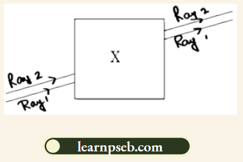
1) What could be the ‘X’ that she placed inside the box to make the rays behave as shown?
- A converging lens
- A parallel-sided glass block
- A plane mirror
- A triangular prism
Answer: 2. A parallel-sided glass block
2) She measured the angles of incidence for both the rays on the left side of the box to be 48.60. She knew the refractive index of the material ‘X’ inside the box was 1.5. What will be the approximate value of angle of refraction?
- 450
- 400
- 300
- 600 (use the value: sin 48.60 = 0.75)
Answer: 3. 300
3) Her friend noted the following observations from this demonstration:
- Glass is optically rarer than air.
- Air and glass allow light to pass through them with the same velocity.
- Air is optically rarer than glass.
- Speed of light through a denser medium is faster than that of a rarer medium.
The ratio: sin of angle of incidence in the first medium to the ratio of sin of angle of refraction in the second medium, gives the refractive index of the second material with respect to the first one.
Which one of the combination of the above statements given below is correct.
2, 4 and 5 are correct.
3 and 4 are correct.
1, 4 and 5 are correct.
3 and 5 are correct.
Answer: 4. 3 and 5 are correct.
4) If the object inside the box was made of a material with a refractive index less than 1.5 then the
- Lateral shift of the rays would have been less.
- Lateral shift of the rays would have been more.
- Lateral shift of the rays would remain the same as before.
- There is not enough information to comment on any of the above statements.
Answer: 1. Lateral shift of the rays would have been less.
Question 2. A concave mirror has focal length 10 cm. Answer the questions using the following table:
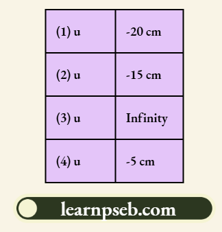
1) If object size is 2 cm, what would be the size of the image in case A?
- 2 cm
- 10 cm
- 4 cm
- Less than 2 cm
Answer: 1. 2 cm
2) Nature of the image when u = -15 cm
- Virtual and inverted
- Real and erect
- Virtual and erect
- Real and inverted
Answer: 4. Real and inverted
3) Nature of the image in case (D)
- Virtual and inverted
- Real and erect
- Virtual and erect
- Real and inverted
Answer: 3. Virtual and erect
4) Position of the image in case (C)
- At centre of curvature
- At focus
- At infinity
- Between focus and centre of curvature
Answer: 2. At focus
5) What is the distance at which the centre of curvature located?
- 5 cm
- 10 cm
- 20 cm
- 15 cm
Answer: 3. 20 cm
Question 3. An object is placed at the following distances from a convex lens of focal length 15 cm:
- 35 cm
- 30 cm
- 20 cm
- 10 cm.
Which position of the object will produce:
1) A magnified real image?
- 35 cm
- 30 cm
- 20 cm
- 10 cm
Answer: 3. 20 cm
Here, f = 15cm and 2f = 30cm
Because a magnified real image is formed when the object is placed between f and 2f.
2) A magnified virtual image?
- 35 cm
- 30 cm
- 20 cm
- 10 cm
Answer: 4. 10 cm
Because a magnified virtual image is formed when the object is placed between f and the lens.
3) A diminished real image?
- 35 cm
- 30 cm
- 20 cm
- 10 cm
Answer: 1. 35 cm
Because a diminished real image is formed when the object is placed beyond 2f.
4) An image of same size as the object?
- 35 cm
- 30 cm
- 20 cm
- 10 cm
Answer: 2. 30 cm
Because an image of same size as the object is formed when the object is placed at 2f.
5) At what distance will the image be formed when an object is placed at 30 cm for this converging lens?
- 10 cm
- 20 cm
- 25 cm
- 30 cm
Answer: 4. 30 cm
When an object is placed at 2F of converging lens the image will be formed at 2F’ at right side of lens and image formed is real, inverted and of same size.
Question 4. The figure given below illustrates the ray diagram for the formation of image by a concave mirror. The position of the is beyond the centre of the curvature of the concave mirror. On basis of the given figure answer the questions given below.
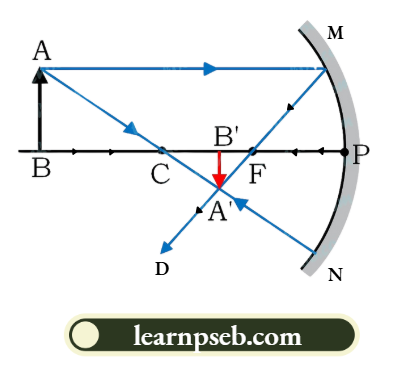
1) If focal length of the concave mirror is 10 cm, the image formed will be at a distance _______.
- Between 10 cm and 15 cm
- Between 10 cm and 20 cm
- Beyond 20 cm
- At 20 cm
Answer: 2. Between 10 cm and 20 cm
Explanation: The focal length of the mirror is 10 cm. This mean, the radius of curvature is 20 cm. From figure, it is clear that the image is formed between the focus and centre of curvature. Thus, the image is formed between 10 cm and 20 cm.
2) In case of concave mirror, the image distance from the pole of the mirror is
- Always positive
- Always negative
- Negative or positive depending upon the position of the object
- None of these
Answer: 3. Negative or positive depending upon the position of the object.
3) If the size of the object in the given figure is 5 cm and the magnification produced is – 0.5. The size of the image is
- -2.5 cm
- -0.1 cm
- 2.5 cm
- 0.1 cm
Answer: 1. -2.5 cm
= h2/h1; h2 = (- 0.5 x 5)/ 10; h2 =- 2.5 cm
4) A negative sign in the magnification value indicate that the image is
- Real and inverted
- Real and erect
- Virtual and erect
- Virtual and inverted
Answer: 1. Real and inverted
5) If the value of magnification is greater than 1 then it indicates that the image formed is
- Diminished
- The same size as that of the object
- Enlarged
- Value of magnification cannot specify whether the image is diminished or magnified.
Answer: 3. Enlarged
Question 5. When a spherical mirror is held towards the sun and its sharp image is formed on a piece of carbon paper for some time, a hole is burnt in the carbon paper. Answer the following questions in reference to the above activity.
1) What is the nature of spherical mirror?
- Convex mirror
- Concave mirror
- Plane mirror
- Plano convex mirror
Answer: 2. Concave mirror
2) Why is a hole burnt in the carbon paper?
- Sun rays are dispersed by the spherical mirror
- The Sun’s heat rays are concentrated at the point of sun’s image
- Sun rays get diverged after reflection from spherical mirror
- Due to atmospheric refraction
Answer: 2. The Sun’s heat rays are concentrated at the point of sun’s image
3) At which point of the spherical mirror the carbon paper is placed?
- Between pole and focus
- Between centre of curvature and focus
- Anywhere between infinity and focus
- At focus
Answer: 4. At focus
4) What name is given to the distance between spherical mirror and carbon paper?
- Image distance
- Object distance
- Focal length
- Principal axis
Answer: 3. Focal length
5) For the above-mentioned spherical mirror, the image formed by it when the object is placed at its centre of curvature is
- Twice the size of the object
- Greater than size of object
- Equal to the size of the object
- Less than the size of the object
Answer: 3. Equal to the size of the object