
PSEB Class 10 Biology Solutions For Chapter 4 Magnetic Effects Of Current
Background
Hans Christian Oersted discovered that electricity and magnetism are interrelated forces. Einstein’s “Theory Of Relativity” later proved that electricity are magnetism are two different aspects of one common phenomenon.
However, in practical terms, electric and magnetic forces behave quite differently – although electric forces are produced by electric charges either at rest or in motion, magnetic forces are produced only by moving charges, and act solely on charges in motion.
Magnet
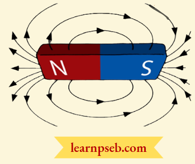
A substance which can attract a piece of iron, cobalt, or nickel is called a magnet. The property by virtue of which a magnet attracts these substances is called magnetism. A magnet has two poles, viz. North Pole and South Pole as shown:
Magnetic Field
The region around a magnet where the effect of a magnet can be felt is called magnetic field. Magnetic field is a vector quantity, i.e., magnetic field has both direction and magnitude. It is created by an electric current or magnetic dipole.
Magnetic Field Lines
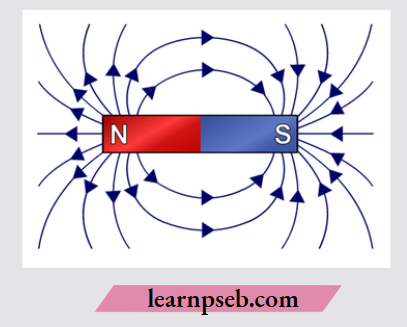
The lines along which the iron filings align themselves, when a bar magnet is brought near them, are called magnetic field lines.
Magnetic field lines are imaginary lines to visualize magnetic field, For Example. When we bring a bar magnet near iron filings, the iron fillings arrange themselves in a pattern as shown. This pattern of lines indicates the magnetic field lines around the bar magnet.
Electromagnetism
The branch of physics that studies the interactions between electric and magnetic fields is called electromagnetism.
Sign Conventions About Magnetic Field Lines
- Magnetic field lines always begin from the N-pole of a magnet and end on the S-pole of the magnet.
- Magnetic field lines form closed curves, i.e, inside the magnet they move from South pole to North pole.
- Magnetic field lines never cross each other. If they did, it would mean that at the point of intersection, the compass needle would point towards two directions, which is not possible.
- The strength of magnetic field is indicated bv the degree of closeness of the field lines. So, magnetic field is the strongest, where the field lines are closest together.
Factors On Which Magnetic Field Depends – Two factors determining amount of magnetic field (B) produced by a current carrying conductor are:
Magnetic field produced is directly proportional to current (I), i.e., B ∝ I
Magnetic field produced is inversely proportional to the radius (r) of the circular loop, i.e, B ∝ 1/r
PSEB Class 10 Physics Solutions Chapter 4
Right Hand Thumb Rule Or Maxwell’s Corkscrew Rule – It gives the direction of magnetic field lines in a current carrying conductor.
According to this rule, if we grasp (or hold) the current-carrying wire in our right hand so that our thumb points in the direction of current, then the direction in which our fingers encircle the wire will give the direction of magnetic field lines around the wire. This is shown in figure below:
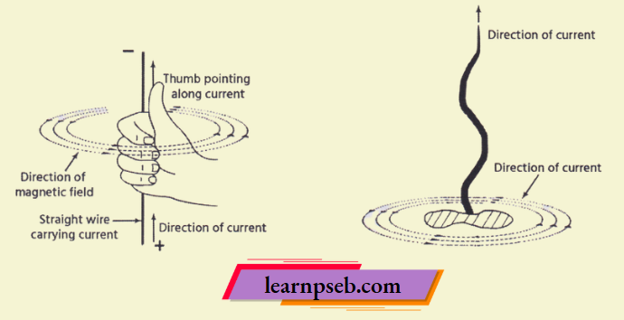
From the above figure, one can easily deduce that if the direction of current in a conductor is reversed, the direction of magnetic field lines will also get reversed.
Maxwell’s Corkscrew Rule
If we consider ourselves driving a corkscrew in the direction of the current, then the direction of the rotation of the corkscrew is the direction of the magnetic field.
Magnetic Field Produced Due To Flow Of Current In A Straight Wire, A Circular Loop, And A Solenoid
1. Magnetic field due to a current through a straight wire – The amount of magnetic field produced is proportional to the current in the conductor. The direction of the current can be found using right-hand thumb rule.
2. Magnetic field due to a current through a circular loop – We know that the magnetic field produced by a current-carrying straight wire depends inversely on the distance (r) from it.
Therefore, the concentric circles representing the magnetic field around it would become larger and larger as we move away from the wire as shown in the figure.
Further, on reaching the centre of the circular loop, the arcs of these big circles will become almost straight and therefore, would appear as straight lines as shown in figure:
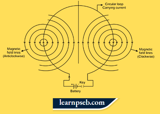
By applying the right hand thumb rule on the above current carrying wire, we can observe the following:
- Every section of the wire contributes to the magnetic field lines in the same direction within the loop.
- Direction of magnetic field at the centre of circular coil is perpendicular to the plane of the coil, i.e., along the axis of the coil.
3. Magnetic field due to solenoid – A solenoid is a long cylindrical coil of insulated copper wire having large number of circular turns as shown in figure:
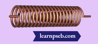
A current carrying solenoid is called an electromagnet because when current is passed through a solenoid, magnetic field is created.
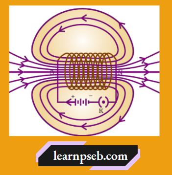
Magnetic field produced by a solenoid is similar to the magnetic field produced by a bar magnet. Due to the presence of turns in the solenoid, magnetic field inside the solenoid is in the form of parallel straight lines, and is the same at all points inside the solenoid as shown in figure.
Strength of magnetic field produced by a current carrying solenoid depends on following factors:
- Number Of Turns In The Solenoid – Larger the number of turns in the solenoid, greater will be the magnetism produced.
- Strength Of Current In The Solenoid– Larger the current passed through solenoid, stronger will be the magnetic field produced.
- Nature of the core material – The use of soft iron rod as core in a solenoid produces the strongest magnetism.
Advantages of electromagnets (current carrying solenoid) over bar magnets
- Unlike bar magnets, electromagnets can be switched on and switched off.
- Magnetic field inside electromagnets can be increased by increasing the number of turns in the coil.
Force on a current carrying conductor in a magnetic field – So far we know that a current-carrying conductor produces a magnetic field around it, i.e, it behaves like a magnet and exerts a force when a magnet is placed in its magnetic field.
In addition to this, the magnetic field also exerts equal and opposite force on the currentcarrying conductor because when the two magnetic fields (i.e., magnetic field produced by the current-carrying conductor and magnetic field due to the nearby magnet) interact with eachother.
There exist attractive or repulsive forces between the two magnetic fields depending upon the direction of the external magnetic field and the direction of the current in the conductor.
The direction of force acting on the current carrying conductor can be determined using Fleming’s Left-Hand Rule.
According to Fleming’s Left Hand Rule, if the left hand is stretched in a way that the forefinger, the center finger, and the thumb are in mutually perpendicular directions.
Then the direction of the forefinger will give the direction of magnetic field, the direction of center finger will give the direction of electric current and the direction of thumb will give the direction of force acting on the conductor as shown:
Factors Affecting Direction Of Force In A Current Carrying Conductor
- Direction of Current – If we change the direction of flow of current, the direction of force will change.
- Direction of Magnetic Field– If we change the direction of poles of magnet, the direction of force will change.
Magnetic Effects Of Current PSEB Class 10 Notes
Factors Affecting Magnitude Of Force In A Current Carrying Conductor
- Amount of current flowing through the conductor – More the amount of current flowing through the conductor, more will be the force.
- Direction of Magnetic Field – Force acting on a current carrying conductor is highest when the direction of magnetic field is perpendicular to the direction of electric current.
Applications Of Magnetism In Real Life
- MRI (Medical Resonance Imaging).
- Magnetic Compass is used during hiking for finding the direction as it always points towards North-South direction.
- Electric Motors – An electric motor is a rotating device that converts electrical energy to mechanical energy. Electric motors are used in hair dryers, electric razors, hair and beard trimmers, washing machines, etc.
- An electric motor works on the principle of magnetic effects of current. An electric motor consists of a rectangular coil placed in a magnetic field. When current is passed through the coil, the coil rotates as a result of the forces acting on it.
Electromagnetic Induction – It is the process of using magnetic fields to produce voltage or current in a closed circuit.
Points To Remember About Electromagnetic Induction
- Electromagnetic Induction was discovered by Michael Faraday.
- Electromagnetic induction is a way of producing electrical current in a circuit by using only the force of a magnetic field, and not batteries.
- Transformers and Generators work on the principle of electromagnetic induction.
Factors Affecting Electromagnetic Induction
- Number of turns of wire in the coil – More the number of turns in the coil, more will be the voltage or current produced.
- Increasing the speed of the relative motion between the coil and the magnet will increase the voltage or current produced.
- Increasing the strength of the magnetic field – If the same coil of wire is moved at the same speed through a stronger magnetic field, more voltage or current will be produced.
Electric Generator – An electric generator, also called a dynamo, is a machine that converts mechanical energy into electricity for transmission and distribution over power lines.
Working Of An Electric Generator
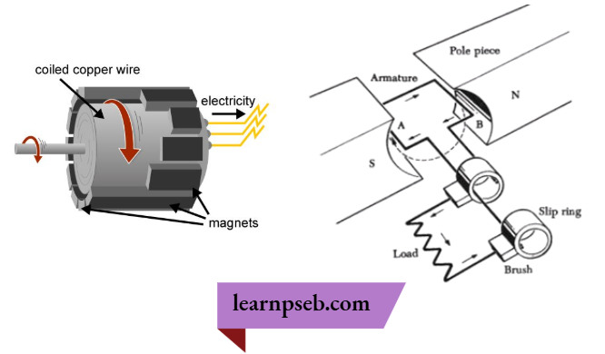
An electric generator works on the principle of electromagnetic induction.
- In an electric generator, a conductor coil, called armature (a copper coil tightly wound onto a metal core), connected to a shaft of a mechanical energy source (such as a motor) is rotated rapidly between the poles of a horseshoe-type magnet.
- The energy to the mechanical energy source is provided by engines operating on fuels such as diesel, petrol, etc.
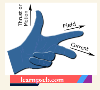
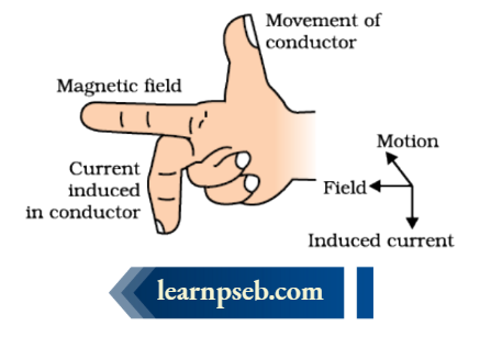
Fleming’s Right Hand Rule (For Generators)- It gives the direction of induced current when a conductor attached to a circuit moves in a magnetic field.
According to Fleming’s Right Hand Rule, if the forefinger indicates the direction of the magnetic field and the thumb shows the direction of motion of the conductor, then the middle finger will show the direction of the induced current.
Please Note:
- Fleming’s left-hand rule is used for electric motors, while Fleming’s right-hand rule is used for electric generators.
- In other words, Fleming’s left hand rule should be used if one were to create motion, while Fleming’s right hand rule should be used if one were to create electricity.
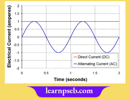
Alternating Current (AC) And Direct Current (DC)
Electric current flows in two ways – Alternating Current (AC) and Direct Current (DC). These are shown graphically in figure below:
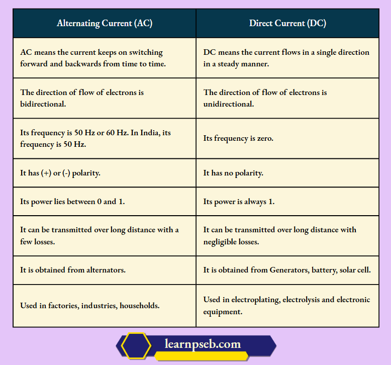
Difference Between Alternating Current (AC) And Direct Current (DC)
Advantages Of Alternating Current (AC) Over Direct Current (DC)
- DC current is normally available from a source like a battery. We cannot have large enough batteries to supply all our needs.
- Electricity needs to be generated continuously to fulfil our needs. In AC, electricity is generated by the rotation of a coil in a magnetic field, whereas a DC generator requires brushes to convert the AC to DC within the machine. Thus, DC requires additional effort and energy.
- Once electricity is generated, it needs to be transmitted over long distances. The transmission is more economical in AC
- Coming to the last stage i.e. usage, though most of the consumers use electricity for lighting in which case AC or DC does not make a difference (that also depends based on the lighting device) the major demand of electricity is for mechanical power. That conversion (electrical to mechanical) is more easily and economically done by AC motor for similar reasons as an AC generator.
Due to the above reasons, use of AC is advantageous over DC.
Disadvantages of Alternating Current (AC) Over Direct Current (DC) – AC cannot be stored.
Domestic Electric Circuits) – Domestic electric circuits use three kinds of wires-
- Live wire (positive) with red insulation cover.
- Neutral wire (negative) with black insulation cover.
- Earth wire with green insulation cover. Earth wire protects us from electric shock in case of leakage of current, especially in metallic appliances, by providing a low resistance path for flow of current in case of leakage.
The flow of current in the domestic circuit follows the following path (as shown in figure below):
PSEB Class 10 Physics Important Questions Chapter 4
Pole → Main Supply → Fuse → Electricity Meter → Distribution Box → To Separate Circuits
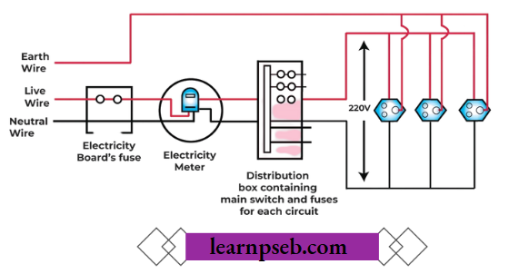
Note: The potential difference between Live wire and Neutral wire in India is 220V.
Short Circuit – Short circuit occurs when live wire accidentally comes in contact with neutral wire. Short circuit can occur due to following reasons:
- Faulty Wire Insulation – If the insulation of wires is damaged, live wire may come in contact with a neutral wire, causing short circuit.
- Damaged Or Loose Wire Connections – This may lead to overheating of the wires resulting in damage to the insulating coating of the wire, and hence short circuit.
Safety Devices To Prevent Short Circuit– Electric Fuse, Earth wire, MCB (Miniature Circuit Breaker).
Overloading– When current drawn is more than current carrying capacity of a conductor, it results in overloading.
Causes Of Overloading
- Accidental hike in voltage supply.
- Use of more than one device in a single socket.
Chapter 4 Magnetic Effects Of Current Reason- Assertion Questions And Answers
The following questions consist of two statements – Assertion (A) and Reason (R). Answer these questions by selecting the appropriate option given below:
- Both A and R are true and R is the correct explanation of A.
- Both A and R are true but R is not the correct explanation of A.
- A is true but R is false.
- A is false but R is true.
Question 1. Assertion (A): On changing the direction of flow of current through a straight conductor, the direction of a magnetic field around the conductor is reversed.
Reason (R): The direction of magnetic field around a conductor can be given in accordance with left hand thumb rule.
Answer: 3. A is true but R is false.
Question 2. Assertion (A): The magnitude of the magnetic field at a point on the axis of a current carrying solenoid is inversely proportional to the current flowing through the solenoid.
Reason (R): The magnitude of the magnetic field at a point on the axis of a current carrying solenoid is directly proportional to the number of turns per unit length of a solenoid.
Answer: 4. A is false but R is true.
Question 3. Assertion (A): A compass needle is placed near a current-carrying wire. The deflection of the compass needle decreases when the magnitude of an electric current in the wire is increased.
Reason (R): Strength of a magnetic field at a point near the conductor increases on increasing the current.
Answer: 4. A is false but R is true.
Question 4. Assertion (A): The strength of the magnetic field produced at the centre of a current carrying circular coil increases on increasing the radius of the circular coil.
Reason (R): Magnetic field strength is inversely proportional to the radius of the circular coil.
Answer: 4. A is false but R is true.
Question 5. Assertion (A): Alternating Current is used in household supply.
Reason (R): AC electric power can be transmitted over long distances without much loss of energy.
Answer: 1. Both A and R are true and R is the correct explanation of A.
Question 6. Assertion (A): A current carrying wire deflects a magnetic needle placed near it.
Reason (R): A magnetic field exists around a current carrying wire.
Answer: 1. Both A and R are true and R is the correct explanation of A.
PSEB Class 10 Science Chapter 4 Solutions
Chapter 4 Magnetic Effects Of Current Case Or Source-Based Questions And Answers
Question 1.
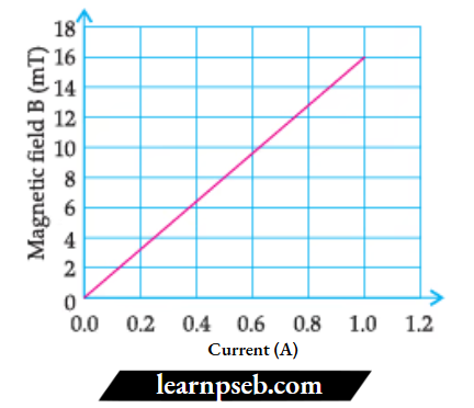
A solenoid is a long helical coil of wire through which a current is run in order to create a magnetic field. The magnetic field of the solenoid is the superposition of the fields due to the current through each coil. It is nearly uniform inside the solenoid and close to zero outside, and is similar to the field of a bar magnet having a north pole at one end and a south pole at the other, depending upon the direction of current flow. The magnetic field produced in the solenoid is dependent on a few factors such as the current in the coil, the number of turns per unit length, etc. The following graph is obtained by a researcher while doing an experiment to see the variation of the magnetic field with respect to the current in the solenoid. The unit of magnetic field as given in the graph attached is in milli-Tesla (mT) and the current is given in Ampere.
1) What type of energy conversion is observed in a linear solenoid?
- Mechanical to Magnetic
- Electrical to Magnetic
- Electrical to Mechanical
- Magnetic to Mechanical
Answer: 3. Electrical to Mechanical
2) What will happen if a soft iron bar is placed inside the solenoid?
- The bar will be electrocuted, resulting in a short circuit.
- The bar will be magnetised as long as there is current in the circuit.
- The bar will be magnetised permanently.
- The bar will not be affected by any means.
Answer: 2. The bar will be magnetised as long as there is current in the circuit.
3) The magnetic field lines produced inside the solenoid are similar to those of ______
- A bar magnet
- A straight current-carrying conductor
- A circular current-carrying loop
- Electromagnet of any shape
Answer: 1. A bar magnet
4) After analysing the graph, a student writes the following statements.
- The magnetic field produced by the solenoid is inversely proportional to the current.
- The magnetic field produced by the solenoid is directly proportional to the current.
- The magnetic field produced by the solenoid is directly proportional to the square of the current.
- The magnetic field produced by the solenoid is independent of the current.
Choose from the following which of the following would be the correct statement(s).
- Only IV
- I and III and IV
- I and II
- Only II
Answer: 4. Only II
5) From the graph, deduce which of the following statements is correct.
- For a current of 0.8 A, the magnetic field is 13 mT
- For larger currents, the magnetic field increases non-linearly.
- For a current of 0.8 A, the magnetic field is 1.3 mT
- There is not enough information to find the magnetic field corresponding to 0.8A current.
Answer: 1. For a current of 0.8 A, the magnetic field is 13 mT
Question 2. Ruchi fixes a sheet of white cardboard on a drawing board. She places a bar magnet in the centre of it. She sprinkles iron filings uniformly around the bar magnet. Then she taps the board gently and observes that the iron fillings arrange themselves in a particular pattern.
1) What does the pattern shape look like?
- Straight lines
- Squares
- Closed curves
- Parallel lines
Answer: 3. Closed curves
2) Why do iron filings arrange in a pattern?
- Due to the poles of a magnet
- Due to the force exerted by the magnet within its magnetic field
- Due to repulsion between the poles and filings
- None of the above
Answer: 2. Due to force exerted by the magnet within its magnetic field
3) What do the lines along which iron filings align represent?
- Magnetic field lines
- Magnetic force
- Magnetic induction
- Magnetic susceptibility
Answer: 1. Magnetic field lines
PSEB Class 10 Science Chapter 4 Solutions
4) What does the crowding of iron filings at the end of the magnet indicate?
- The magnetic field is weak at the poles and stronger in the middle
- The magnetic field is stronger at the poles and weaker at the middle
- Magnetic field strength goes on decreasing from the north to the south pole
- Magnetic field strength goes on decreasing from the south to the north pole
Answer: 2. The Magnetic field is stronger at the poles and weaker at the middle
5) How is the strength of the magnetic field is indicated?
- Magnetic field strength cannot be indicated by magnetic field lines
- Far the magnetic field lines, more is the magnetic strength
- The closer the magnetic field lines are the magnetic field strength
- The closer the magnetic field lines, more is the magnetic strength
Answer: 4. Closer the magnetic field lines, more is the magnetic strength
Question 3. The magnetic field at any point is the combined effect of the magnetic field due to the current in the wire and the magnetic field of the Earth. Iron filings, when placed near the wire carrying current, are arranged in circles due to the magnetic field produced by the current flowing through the wire. However, at a point far away from the wire, the magnetic field due to the Earth is predominant as compared to the magnetic field due to the current, due to which the iron filings are arranged in straight lines. The point where the two fields are equal and opposite is called the neutral point. At the neutral point, the net magnetic field is zero, and the compass needle at this point rests in any direction.
1) How are the magnetic field lines at the point near the straight current-carrying conductor?
- A concentric circles pattern whose centre lies on a wire
- Uniform and parallel line pattern
- Spiral pattern
- Zig-zag pattern
Answer: 1. Concentric circles pattern whose centre lies on the wire
2) To what parameter is the magnitude of the magnetic field produced by the straight conductor directly proportional?
- Distance from the conductor
- Strength of current in wire
- External forces acting on the wire
- Nature of material
Answer: 2. Strength of current in wire
3) Which rule is used to find the direction of the magnetic field produced by the straight current-carrying conductor?
- Maxwell’s left-hand thumb rule
- Maxwell’s right-hand thumb rule
- Fleming’s left-hand rule
- Fleming’s right-hand rule
Answer: 2. Maxwell’s right-hand thumb rule
4) What, according to the rule, will be the direction of the current when lines of the magnetic field are in the anti-clockwise direction?
- Downward direction
- Left direction
- Upward direction
- Right direction
Answer: 3. Upward direction
5) SI unit of magnetic field is
- Gauss
- Coulomb
- Weber
- Tesla
Answer: 4. Tesla
Question 4. The magnetic field at any point is the combined effect of the magnetic field due to the current in the wire and the magnetic field of the Earth. Iron filings, when placed near the wire carrying current, are arranged in circles due to the magnetic field produced by the current flowing through the wire. However, at a point far away from the wire, the magnetic field due to the Earth is predominant as compared to the magnetic field due to the current due to which the iron filings are arranged in straight lines. The point where the two fields are equal and opposite is called the neutral point. At the neutral point, the net magnetic field is zero and the compass needle at this point rests in any direction.
- How are the magnetic field lines at the point near the straight current-carrying conductor?
- To what parameter is the magnitude of the magnetic field produced by the straight conductor directly proportional?
- Which rule is used to find the direction of the magnetic field produced by the straight current-carrying conductor?
Answer:
- The magnetic field lines around the straight conductor carrying current are concentric circles whose centre lies on the wire.
- The magnitude of the magnetic field is directly proportional to the current passing through the wire,
- Maxwell’s right-hand thumb rule is used to find the direction of the magnetic field produced by a straight current-carrying conductor.
Question 5. Andre Marie Ampere suggested that a magnet must exert an equal and opposite force on a current-carrying conductor, which was experimentally found to be true. But we know that current is due to charges in motion. Thus, it is clear that a charge moving in a magnetic field experiences a force, except when it is moving in a direction parallel to it. If the direction of motion is perpendicular to the direction of magnetic field, the magnitude of force experienced depends on the charge, velocity (v), strength of the magnetic field (B), and sine of the angle between v and B. The Direction of magnetic force is given by Fleming’s left-hand rule.
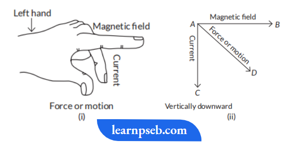
1. If an electron is travelling horizontally towards east. A magnetic field in vertically downward direction exerts a force on the electron along which direction?
2. If a charged particle is moving along a magnetic field line, what would be the magnetic force on the particle?
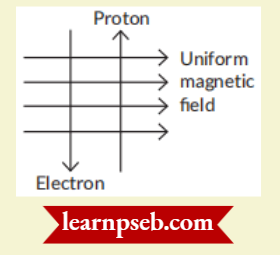
3. A uniform magnetic field exists in the plane of paper pointing from left to right as shown in figure. In the field, an electron and a proton move as shown. Where do the electron and the proton experience the force?
Answer:
- Fleming’s left hand rule is used to determine the direction of force on electron i.e., in south direction.
- The angle between velocity and magnetic field is zero. Therefore, magnetic force on the particle is zero.
- As the direction of current is taken opposite to the direction of motion of electrons, therefore, current from the motion of electron and proton is in the same direction, i.e., from bottom to top. Now, according to Fleming’s left hand rule, the electron and the proton experience forces both pointing into the plane of paper.
Question 6. A current-carrying wire produces a magnetic field around it. The phenomenon in which an electromotive force and current (if the conductor is in the form of a closed circuit) is induced by changing a magnetic field (or by passing magnetic field lines) through it is called electromagnetic induction. The emf so developed is called induced emf and the current made to flow is called induced current.
The cause of induced emf was discovered by Faraday and Flenry. It can be concluded that the induced current flows in a conductor as long as the magnetic lines of force change within the conductor. In case of relative motion i.e., motion of coil w.r.t to magnet or vice versa, the direction of the current flowing in the conductor is determined by the direction of the relative motion of the conductor with respect to the magnetic field. The induced emf or current is directly proportional to the rate of change in magnetic field.
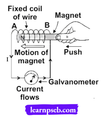
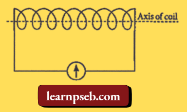
1. A student connects a coil of wire with a sensitive galvanometer as shown in the figure. Where will he observe the deflection in the galvanometer of bar magnet?
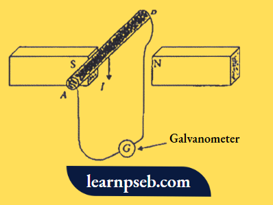
2. A conducting rod AB moves across two magnets as shown in the figure and the needle in the galvanometer deflects momentarily. What is the name of this physical phenomenon?
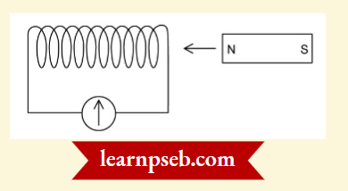
3. A bar magnet is pushed steadily into a long solenoid connected to a sensitive meter.
Answer:
- The deflection in the galvanometer can be seen if the bar magnet moves towards or away from the coil parallel to the axis of the coil.
- If the needle of the galvanometer deflects, it means there is a change in a magnetic field and current is induced.
- By Faraday’s law of electromagnetic induction, the e.m.f. induced in a conductor is proportional to the rate of change of magnetic lines of force linking the circuit. Hence, by pushing the magnet faster, the rate of change of magnetic lines will increase. This results in larger induced e.m.f.., and hence, larger deflection of the meter.